
How Can We Help?
CORE4 Mazda MX5 MK2.5 01-05 PnP Install Guide
The CORE4 ECU fits into the factory ECU case and can then plug straight into the stock wiring in place of the original ECU, however some hardware changes are either recommended or are desirable in most installations.
CONNECTING TO THE ECU
USB DRIVER
Our CORE4 uses the Silicon Labs CP2102 USB-Serial chip for the PC connection.
Windows and other OS’s should automatically download and install the correct drivers for it.
But if you are having problems and not seeing a COM port in TunerStudio download and install the drivers manually from here: https://www.silabs.com/developers/usb-to-uart-bridge-vcp-drivers
TUNING SOFTWARE
Tuner Studio is the tuning interface software used by Speeduino. It runs on Windows, Mac and linux and provides configuration, tuning and logging capabilities.
If you haven’t already, grab a copy of Tuner Studio from EFI Analytics
Tuner Studio is available for Windows, Mac and linux and will run on most PCs as it’s system requirements are fairly low.
The current minimum version of TunerStudio required is 3.0.7, but the latest version is usually recommended.
Refer to the TunerStudio section of our Youtube video to help set up your project.
SPEEDUINO GETTING STARTED
If you have purchased a PnP ECU from us, it will have a starting map on, so do NOT follow the loading the tune section.
SENSOR SETUP
MAP HOSE CONNECTION
Run 3mm ID silicone hose from the ECU (onboard sensor or barb, model depending) to the inlet manifold AFTER the throttle body.
TEMPERATURE SENSOR CALIBRATION
Your new ECU will be pre-calibrated for the default MX5 coolant sensor and default MX5 air temperature sensor.
It is wise to check that the air temperature and coolant temperature readings are sane before attempting a first start.
If you are using sensors other than specified above you will need to recalibrate.
THROTTLE POSITION SENSOR
Before Speeduino can work correctly with your engine, you will also need to Calibrate the Throttle Position Sensor. This must be done using the throttle body and TPS used on the engine. It is best to do this while the throttle body is installed on the engine.
Open the Tools menu and select Calibrate TPS: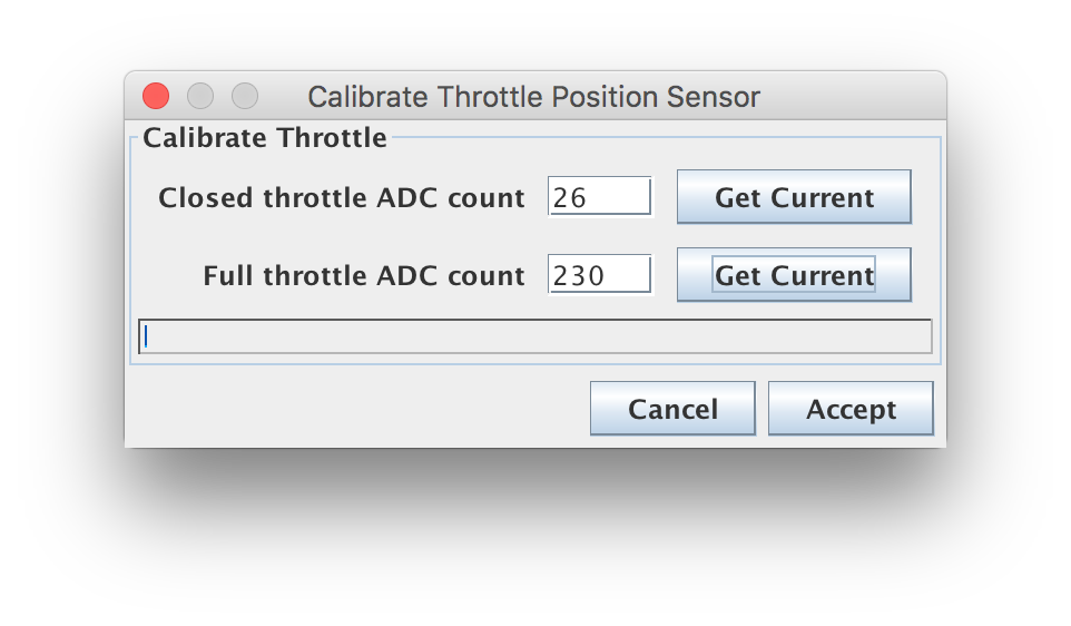
With the throttle closed, click the Get Current button beside the Closed Throttle ADC count field. Then move the throttle to full open and hold it there. Then click the Get Current button beside the Full Throttle ADC count field.
Click Accept to save the information to Speeduino.
AFR/LAMBDA/OXYGEN SENSOR

First set the jumper on the left of the mainboard. This determines whether you are using the optional onboard wideband or using a signal from an external controller routed through the original factory narrow band pin (4W)
Open the Tools menu again and select Calibrate AFR Table:
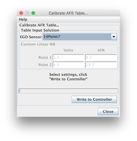
Select your Oxygen Sensor sensor from the Common Sensor Values drop-down list. If you are using a custom Oxygen Sensor controller, select Custom Linear WB and then you can enter the values for Volts and AFR at two points (should be published in the controller manual).
If you have selected the inbuilt Wideband option, you should use the DIY-EFI TinyWB option.
This will have been done already for you on any CORE4 Based ECU.
Click Write to Controller to send this information to your ECU
AUX CONNECTOR
| PIN NUMBER | PURPOSE |
| 1 | Ground |
| 2 | Spare in 2 (TunerStudio ‘A14’) |
| 3 | Spare Lowside (TunerStudio ’37’) |
| 4 | Ignition 3 |
| 5 | Boost Out |
| 6 | 5V Sensor Supply |
| 7 | Spare in 1 (TunerStudio ‘A13’) |
| 8 | Ethanol Sensor |
| 9 | Ignition 4 |
| 10 | VVT Out |
TROUBLE SHOOTING
SENSOR VALUES MIXED UP
This is most likely caused by using a basemap from another ECU that is not compatible.
In TunerStudio, click the settings button.
Set the board layout to DIY-EFI CORE4 v1.0
Power cycle the ECU and the sensors should now respond as expected.

PIN MAPPING
| ECU pin | Purpose | TunerStudio Pin (Empty = Board Default) |
|---|---|---|
| 2A | INJ 1 OUT | |
| 2B | FAN OUT | |
| 2C | AC FAN OUT | NA – Direct to switch |
| 2D | INJ 4 OUT | |
| 2G | INJ 2 OUT | |
| 2J | INJ 3 OUT | |
| 2K | AC CLUTCH OUT | NA – Direct to switch |
| 2M | FUELPUMP OUT | |
| 2N | VICS OUT | 36 |
| 2P | 12V SW | NA – 12V Switched Power In |
| 2Q | IDLE OUT | |
| 2R | CEL OUT | Not Connected |
| 3A | GND | NA – Power Ground |
| 3B | GND | NA – Power Ground |
| 3C | OEM: PURGE Solenoid – USED FOR BOOST | Boost Board Default |
| 3F | IGN 1 OUT | |
| 3H | MAIN RELAY | NA – Trigger For Main Relay |
| 3I | IGN 2 OUT | |
| 3M | Field | NA – Alternator Control |
| 3O | TACHO OUT | |
| 3T | VSS IN | |
| 3V | CAM IN | |
| 3Y | CRANK IN | |
| 4A | GND | NA – Power Ground |
| 4D | 12V SW | NA – 12V Switched Power In |
| 4F | AC SWITCH IN | A13 (If JP5 Closed) |
| 4H | Clutch in (Alternative) | |
| 4I | Clutch in | |
| 4L | 5V Sensor Supply | NA – Sensor Supply |
| 4N | IAT Sensor | |
| 4O | GNDA | NA – Sensor Ground |
| 4P | CLT Sensor | |
| 4R | VVT OUT | |
| 4S | Ignition Switch in | NA – Ignition Switch Trigger |
| 4V | TPS Sensor | |
| 4W | O2 Sensor | |
| 4AF | 12V SW | NA – 12V Switched Power In |